Part 3 Tech&Phy from
Introduction
Due to the cvoid-19 influence, the main materials I use to make my products are from he arduino and the materials I had at home. In my original plan, I was looking forward to using the laser cutter and 3D printer in the school's workshop to make the bracelets and base stations look more appropriate.
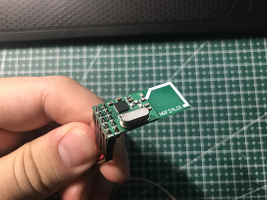
Wireless Transmitter
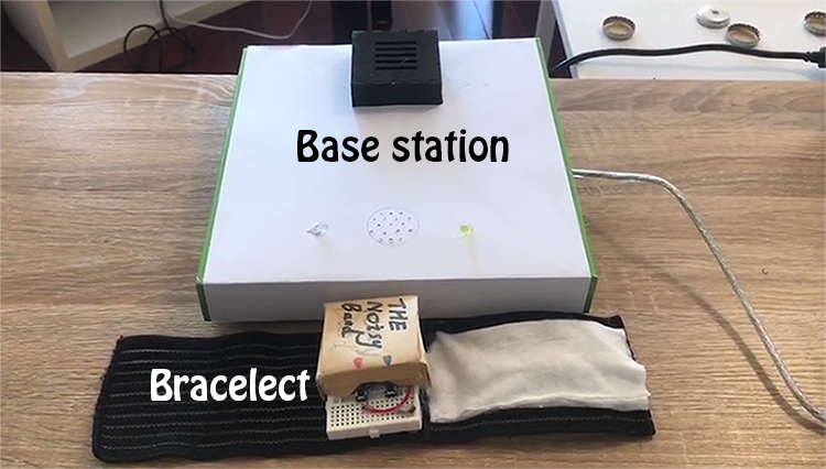
The wireless signal transmitter/receiver is the core function of my product. On my product, two wireless transmitters are installed in the bracelet and the base station respectively. Through the two-way communication between the bracelet and the base station, my product can achieve various functions such as triggering the vibration of the bracelet, and the base station stops making noise after the bracelet leaves the signal range.
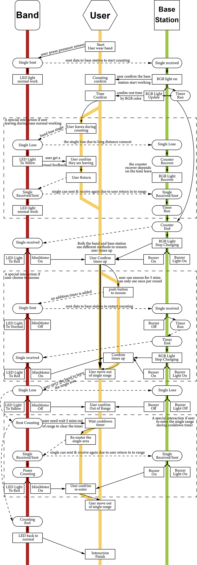
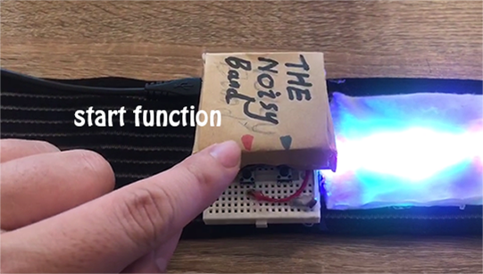
When both the bracelet and the base station are powered on and start working, both the bracelet and the base station will continue to send a signal to each other to confirm whether the other is in working range. When the user presses the start button, the bracelet will send to the base station a "start timing" signal, the base station will trigger the timer light and start timing after receiving the signal. After the counting is over, the base station will send a "time out" signal to the bracelet, and at the same time, the buzzer on base station will generate Noise. After receiving the "time out" signal from the base station, the bracelet will also change the colour of the LED light and start vibrating.
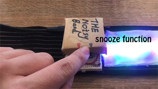
In order to stop the noise of the base station and the bracelet, users can first use the "snooze" function, after pressing the snooze button, the bracelet will send a "snooze" signal to the base station. At this time, the bracelet and the base station will fall into a 5-minute silence. When the snooze time is over, the bracelet will send another "time out" signal to the base station. The base station and the bracelet then will continue to trigger the alarm.
Another way to completely turn off the alarm is that when the bracelet and the base station no longer receive the others confirmation signal for 5 seconds, the bracelet is recognized has left the signal reception range of the base station. When the bracelet leaves the reception range of the base station in the alarm state, the bracelet and the base station will enter the "cooldown time", and in the state of the "cooldown time", the bracelet and the base station will continue to try to establish contact by keep sending and receiving signals, once the bracelet re-enters the signal range of the base station within the "cooldown time", it will re-start the alarm. The alarm will only be turned off after the bracelet stays outside the signal range for 5 minutes, the bracelet and the base station then will return to the initial state, waiting for the next round of timing to begin.
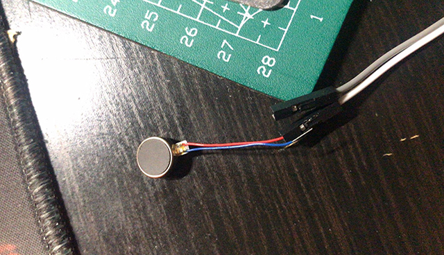
MiNi Motor
The mini motor is installed in the bracelet. In order to provide users with vibration feedback equipment, when the alarm is triggered, the mini motor placed at the bottom of the bracelet will vibrate, thereby giving the user a tactile reminder.

LED lights on bracelet
LED lights are light strips installed on the bracelet. The main function of LED lights is to provide users with visual feedback, so that users can understand the current status of the bracelet. The LED light of the bracelet has the following states:
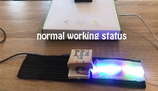
1. Normal working state: The color of the bracelet is a combination of red, bule green and white, and the bracelet will show this color when it is in standby or waiting for the counting of the base station.

2. Alarm status: The color of the bracelet is red and white flashing alternately. The bracelet will show this color when the alarm is triggered.

3. Snooze status: The color of the bracelet flashes yellow, the bracelet will show this color when the snooze mode is triggered.
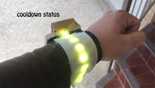
4. Cooldown state: The color of the bracelet is always yellow, and the bracelet will display this color after the alarm is triggered, and the user takes the bracelet away from the signal range of the base station
Buttons
The button on the bracelet is the user's main method of interaction. The button marked in red indicates the "start timer" function, while the button marked in blue indicates the "snooze" function.
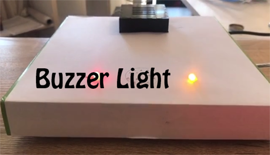
Buzzer
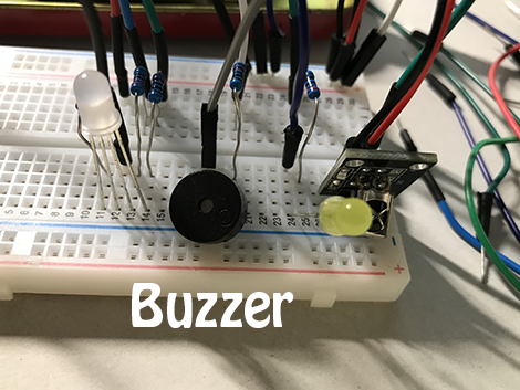
The buzzer located on the base station is mainly used to make unbearable noise and force the user to leave. The Buzzer indicator gives the user some visual assistance to confirm whether the buzzer is currently on.
LED Lights on base station
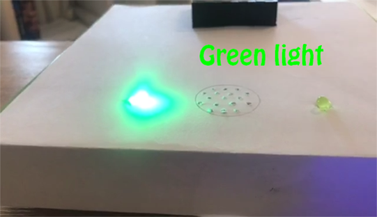
The LED located on the base station is mainly used to indicate the time remaining before the user gets up. The LED lights on the base station have the following states:
1. Green: The remaining time is 30mins to 10mins.
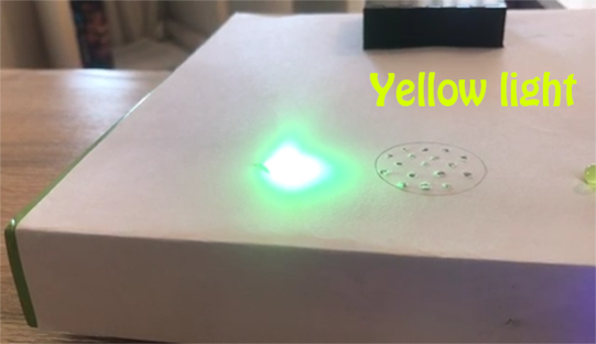
2. Yellow: the remaining time is 10mins to 3mins
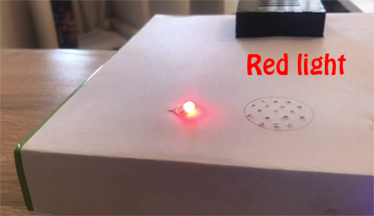
3. Red: The remaining time is within 3mins.